
R = Radius(반지름)
C = Chamfer(모따기)
주서 = Note, General information in drawing
도시되고 지시없는 C2, 라운드는 R3 = shown and not indicated chamfer is C2 and round is R3
실선(Continuous line) : Outline of an object, Lineweight 3.5
점선(Hidden line) : A line that is not visible on the outside of an object, but is visible through x-ray. Lineweight 2.5
중심선(Center line) : A line indicating the center of a circle, Lineweight 1.8
A line that represents the center of symmetry.
중심표시(Center mark) : A line that marks the center of a circle or arc, Lineweight 1.8
치수선(Dimension line) : Line with arrows on the left and right. Lineweight 1.8
치수보조선(Dimension extension line) : A line must specify the starting and ending points on the outline of an object.
# Korean 3D Printer Operation Technician Certification Guide - For International Students
Hello international students studying in Korea! Today I'd like to introduce you to the 3D Printer Operation Technician certification, which can enhance your competitiveness in the Korean job market.
## What is the 3D Printer Operation Technician Certification?
The 3D Printer Operation Technician certification is a national technical qualification administered by the Human Resources Development Service of Korea (HRD Korea). It verifies your ability to design and create products using 3D printing technology. As demand for 3D printing skills continues to grow across manufacturing and various industries, the value of this certification has also increased.
## Benefits of Certification
- Preferential treatment when applying for jobs at Korean companies (especially in manufacturing and engineering)
- Recognition of practical skills and potential salary advantages
- Competitive edge when entering R&D and product design fields
- Proof of technical expertise for entrepreneurship
- Possible advantage in visa extension evaluations
## Exam Content
The 3D Printer Operation Technician exam consists of written and practical tests.
### Written Test
- Basic 3D printing theory
- 3D modeling and design principles
- 3D printer equipment operation and maintenance knowledge
- Fundamentals of materials engineering
### Practical Test
- 3D modeling software proficiency
- 3D printer operation and output production
- Post-processing and quality inspection
## How to Prepare
1. **Language Preparation**: The exam is conducted in Korean, so basic Korean language skills are necessary. Learning technical terminology is particularly important.
2. **Study Materials**: Utilize textbooks and practice questions provided by HRD Korea. These are available at university libraries or online bookstores.
3. **Practical Experience**: Gain hands-on experience by participating in 3D printing classes or workshops at your university.
4. **Study Groups**: Forming study groups with Korean students can help you improve both language skills and technical knowledge.
## Application Process
1. Register and log in to the Q-Net website (http://www.q-net.or.kr)
2. Apply during the registration period
3. Foreign nationals can apply using their Alien Registration Card information
4. Pay the examination fee (Written test: approximately $20, Practical test: approximately $70)
## Exam Schedule
The exam is held 2-3 times per year, with exact dates available on the Q-Net website. Typically, you must pass the written test before taking the practical test. The written test certification is valid for 2 years.
## Tips for International Students
- Create a separate glossary of Korean technical terms for studying
- Check if your university's international student center offers exam preparation assistance
- Actively participate in 3D printing clubs or department activities to gain practical experience
- Attend information sessions or workshops for foreign nationals offered by HRD Korea when available
The 3D Printer Operation Technician certification can be highly beneficial for international students planning to work or start a business in Korea after graduation. It's a great opportunity to receive official recognition for skills that are essential in future industries, so if you're interested, we encourage you to give it a try!
Feel free to leave questions in the comments section. We'll be sharing more detailed preparation guides in the future.
CHAPTER 1. PART MODELING

단일 폐곡선 : single closed curves(1 closed area)
단일 개곡선 : single opened curves(Used for sheet metal)
다중 폐곡선 : Multiple closed curves(Multiple closed area)
The origin is a good place to start if you know where Part 1 and Part 2 will be assembled.
부품1과 부품2가 조립되는 위치를 원점으로 정해놓으면, 기준을 정하기 좋다.
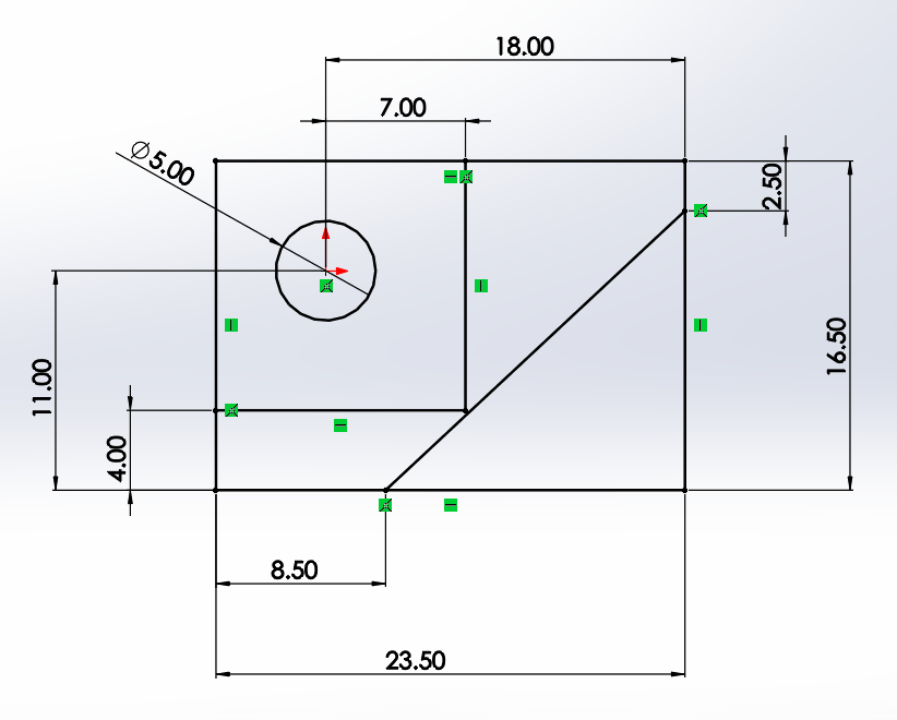
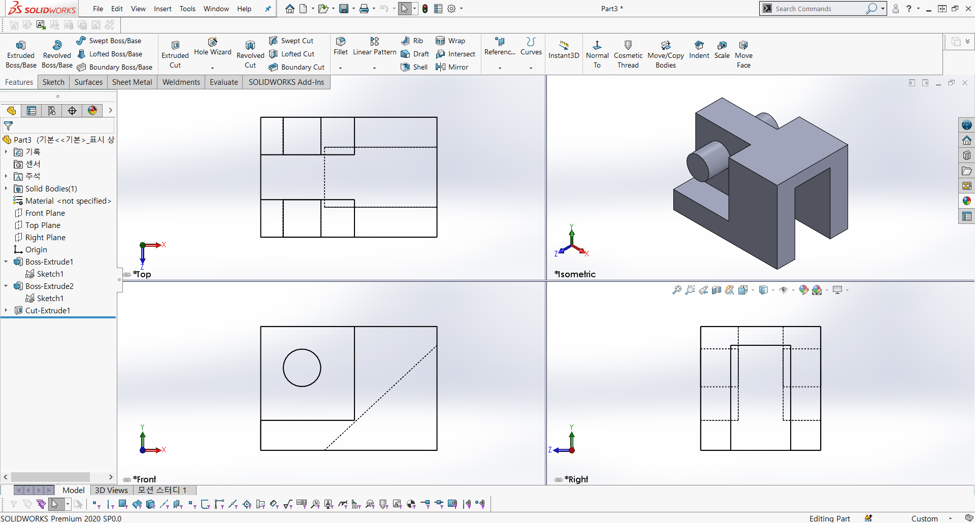
You can think of the dimensions as replicating the dimensions in the drawing.
Sketching with Multiple Sketch Methods.
Adding dimensions that aren't in the drawing can be tricky for beginners.
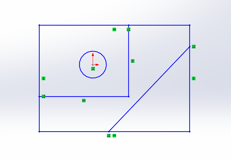
Sketches appear in black when they are fully defined.
치수는 도면에 나와있는 치수를 그대로 옮겨놓는다고 생각하면 된다.
다중스케치방법으로 스케치한다.
도면에 없는 치수를 넣는건 초보자에게는 놓치는 요소가 많을 수 있다.
스케치는 완전정의가 되면 검은색으로 나타난다.
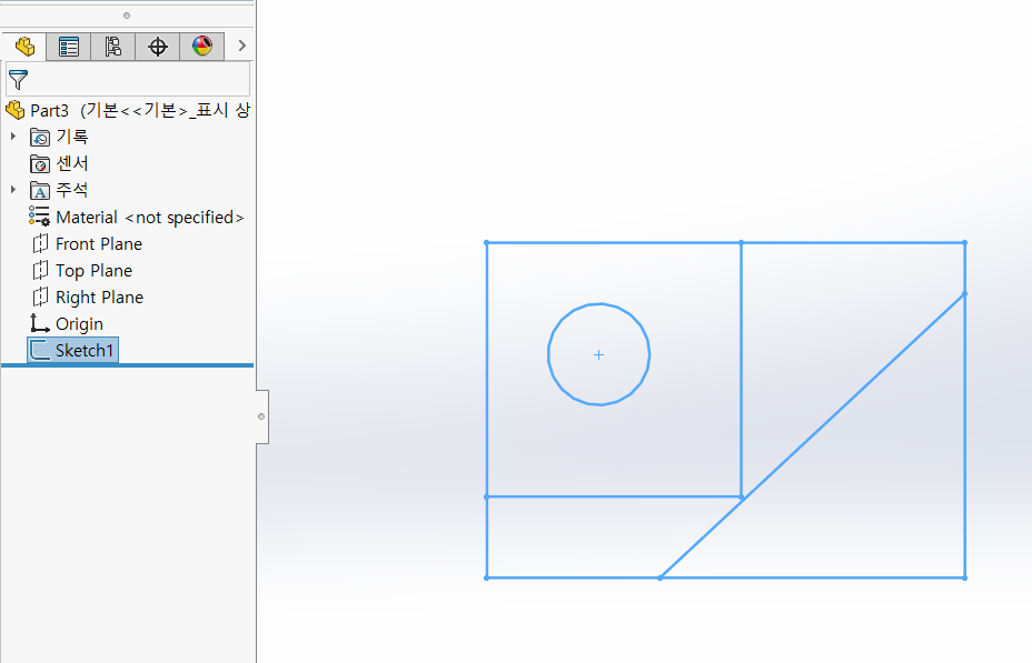
When the sketch is complete, and the sketch is selected, the sketch color appears to be light blue.
스케치가 완료되고, 스케치가 선택이 되면, 스케치 색상은 하늘색으로 나타난다.
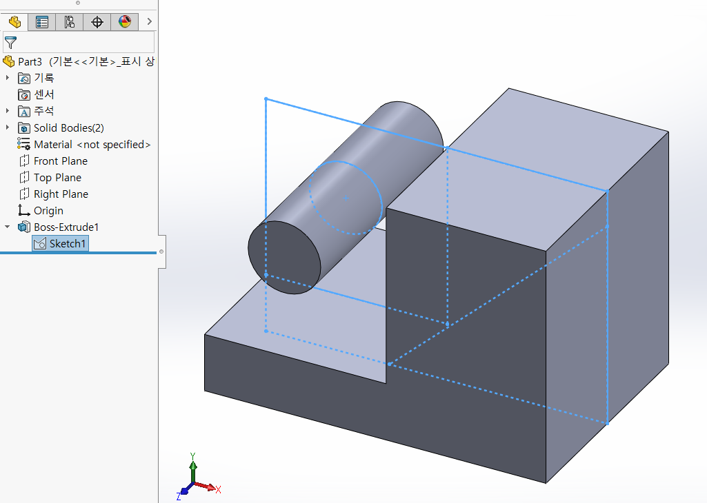
In sketches created using multisketching, you must select regions.
Caution: Be careful not to select lines.
다중스케치로 작업된 스케치에서는 영역을 반드시 선택해주어야 한다.
주의사항 : 선을 선택하지 않도록 조심한다.
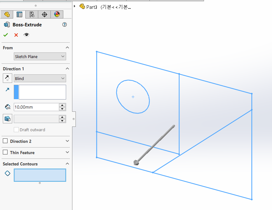
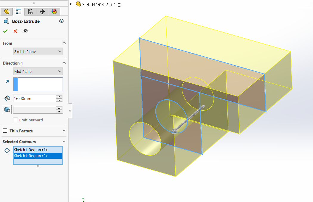
Select Regions of equal thickness,
Extrude direction: Extrude from the center plane as it is symmetrical when viewed from a top view.
같은 두께를 가지는 영역을 선택하고,
돌출방향 : 평면도를 봤을 때, 대칭형상이므로 중간평면을 기준으로 돌출한다.
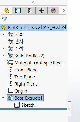
The sketch you used as an extrusion exists in the subtree of the extrusion.
돌출로 사용했던 스케치는 돌출의 하위 트리에 존재한다.
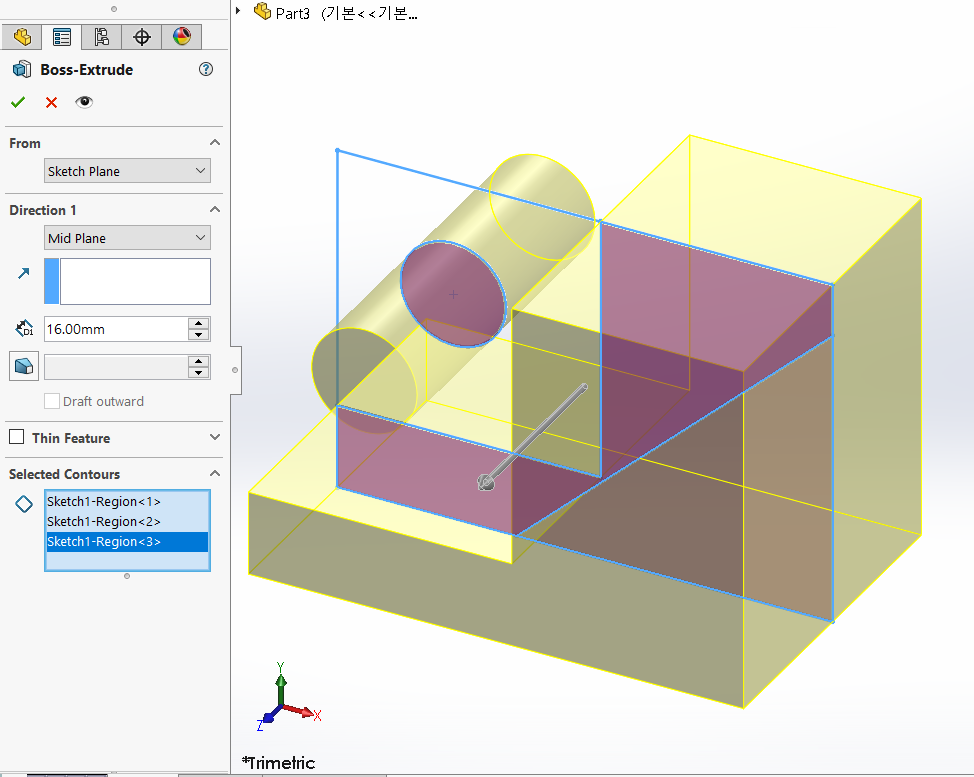
Extrude1 Select the included sketch to create extrusions with different thicknesses.
돌출1 포함된 스케치를 선택하여 다른 두께를 가진 돌출을 한다.
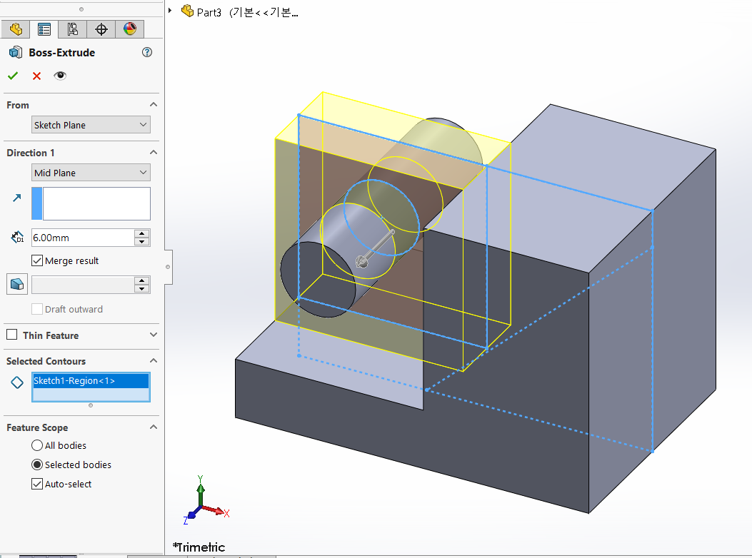
Select a Region that is 6 mm thick
Orient the extrusion to the mid-plane.
두께 6mm애 해당하는 영역을 선택
돌출방향은 중간평면으로 한다.
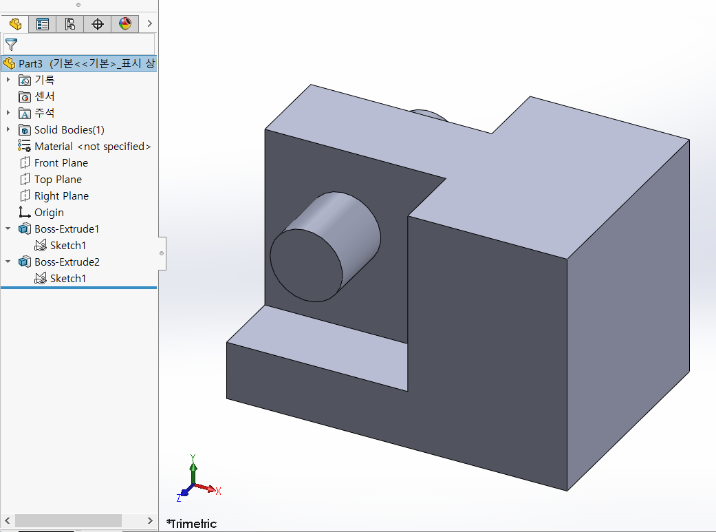
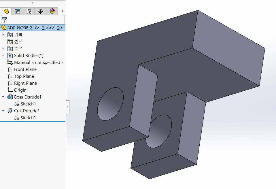
Extrusions are 1 and 2 and Sketches are only Sketch 1 because they were used together.
돌출은 1,2가 있고, 스케치는 같이 사용 했기 때문에 스케치1만 있다.
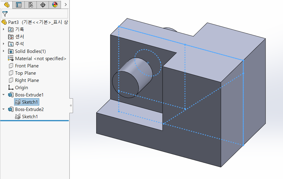
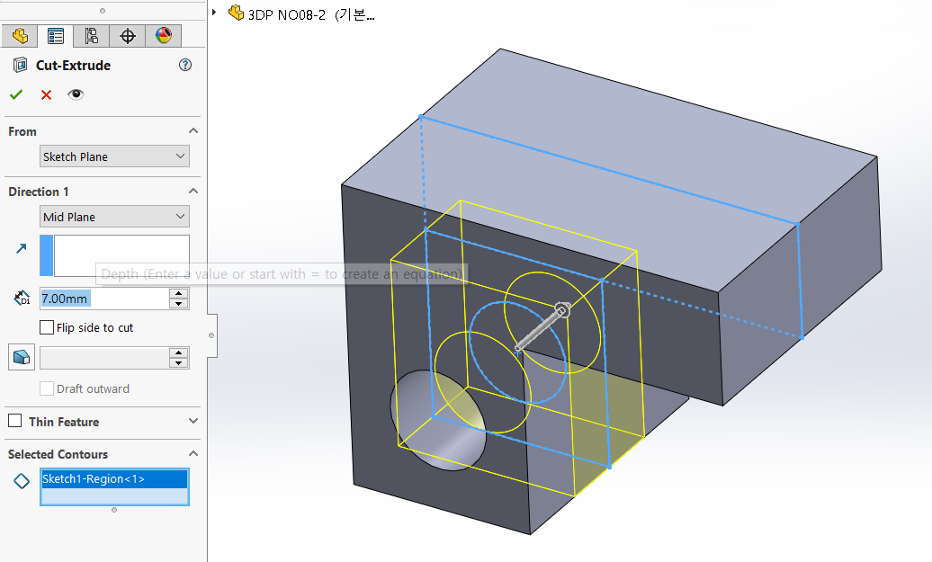
Again, we share and use the sketch to extrude-cut.
이번에도 스케치를 공유해서 사용해서 돌출-컷을 한다.
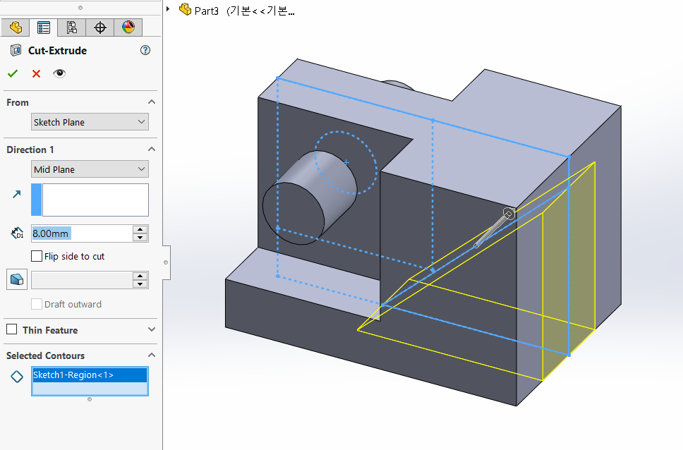
Select a Region for the right extrusion cut,
extrude direction to the mid-plane.
오른쪽 돌출-컷에 대한 영역을 선택하고,
돌출방향은 중간평면으로 한다.
The basic geometry is finalized.
기본적인 형상이 마무리되었다.

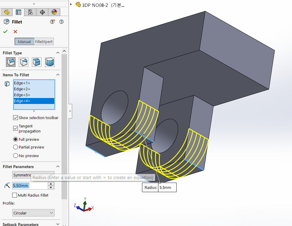
Three fillets are labeled in the drawing as R7, R5.5, and R3.
R3 is in the NOTE.
You should start with the larger fillets.
필렛은 R7, R5.5, R3 세가지가 도면에 표기되어 있다.
R3은 주서란에 있다.
필렛은 큰값부터 넣어주는게 좋다.
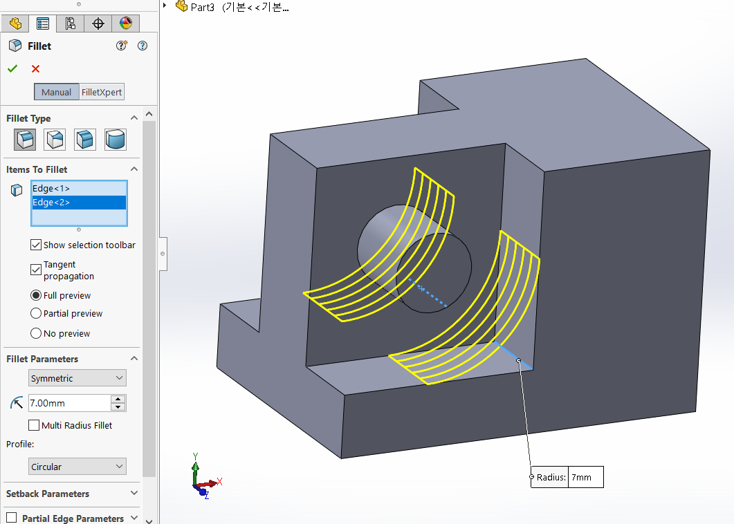
Select 2 corners corresponding to R7
R7에 해당하는 모서리 2개소 지정
When you finish filleting and hit enter, the command you ran earlier will be re-executed.
필렛을 마무리하고, 엔터를 치면, 좀 전에 실행했던 명령이 재실행된다.
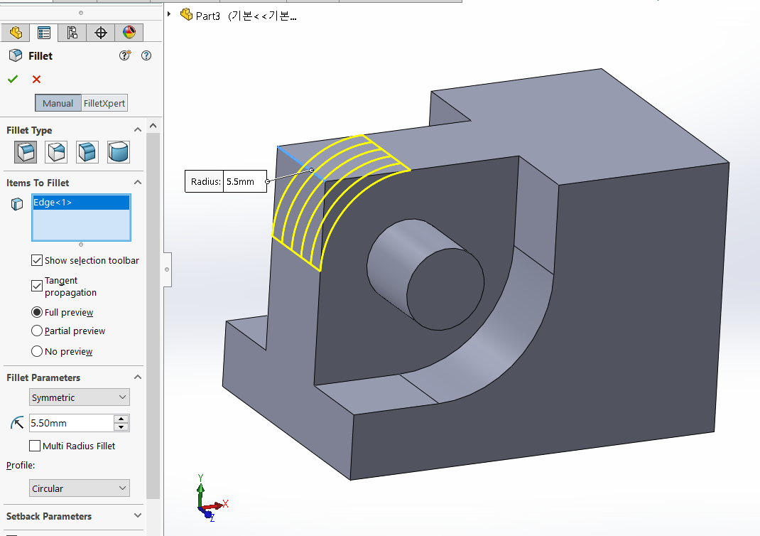
R5.5 Select the corresponding corner.
R5.5애 해당하는 모서리를 선택한다.
When you finish filleting and hit enter, the command you ran earlier will be re-executed.
필렛을 마무리하고, 엔터를 치면, 좀 전에 실행했던 명령이 재실행된다.
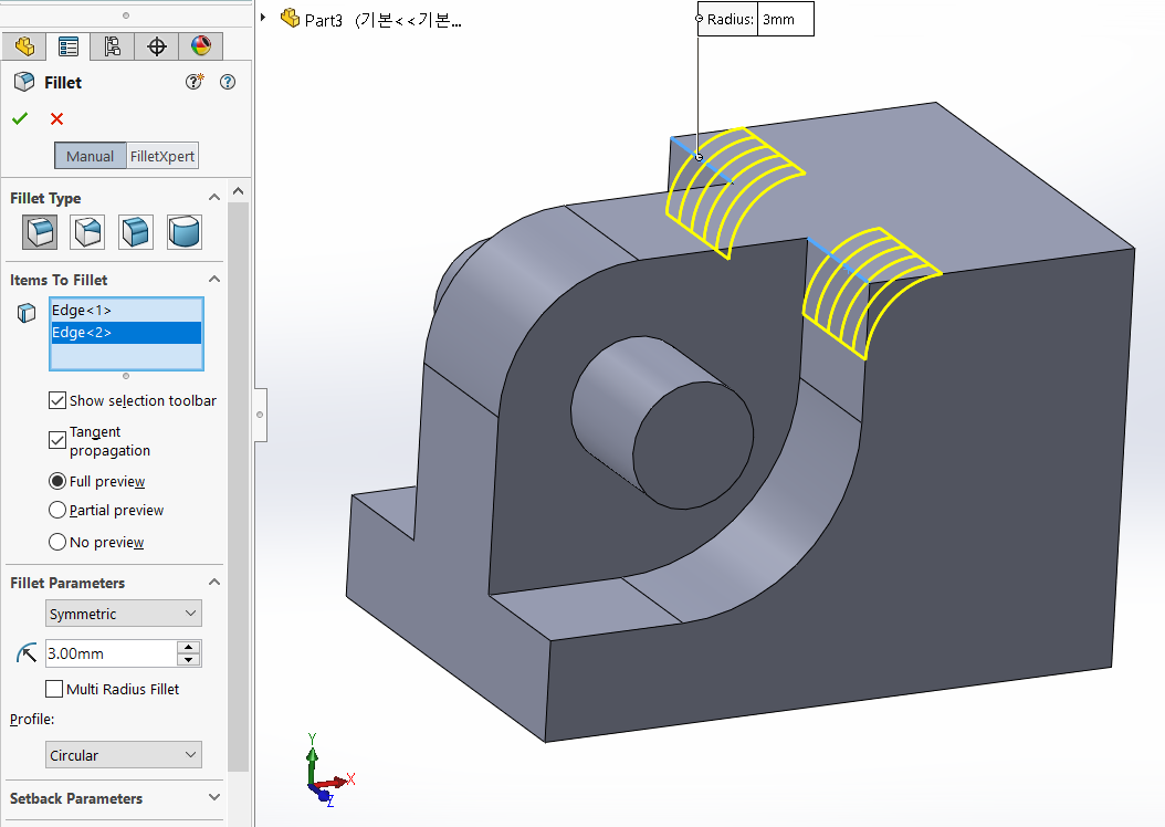
R3 Select the corresponding corner.
R3에 해당하는 모서리를 선택한다.
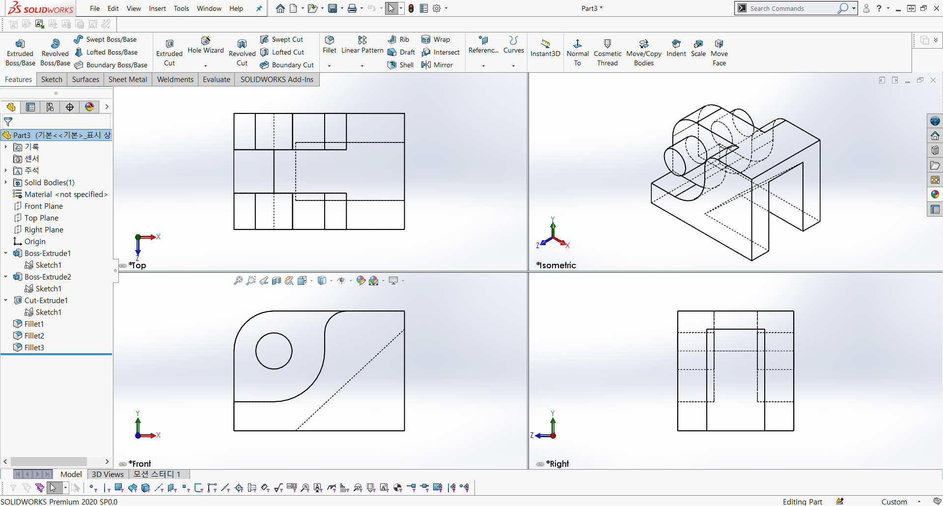
Part 1 is complete.
부품1이 마무리 되었다.
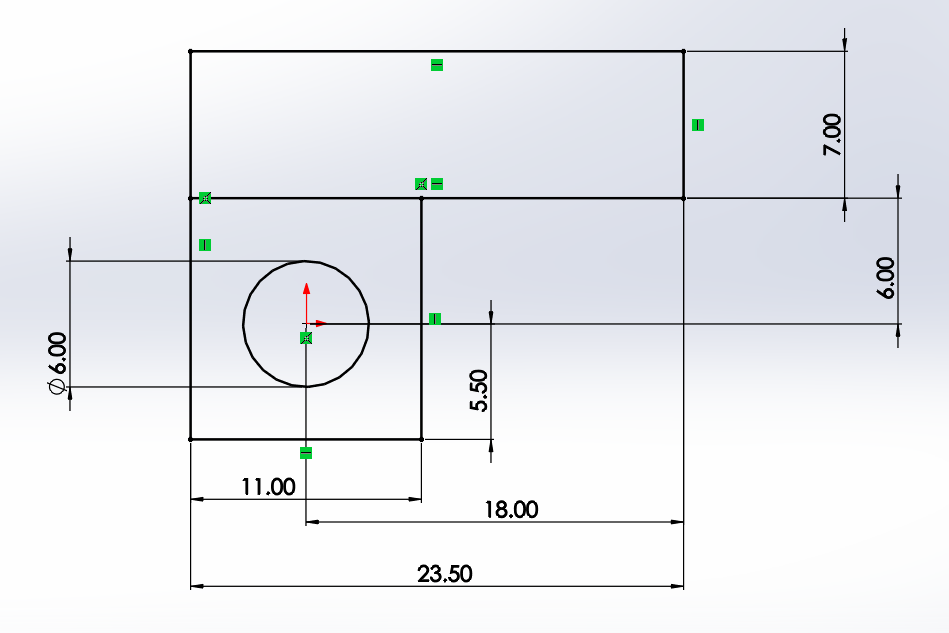
Part Name : No08-1
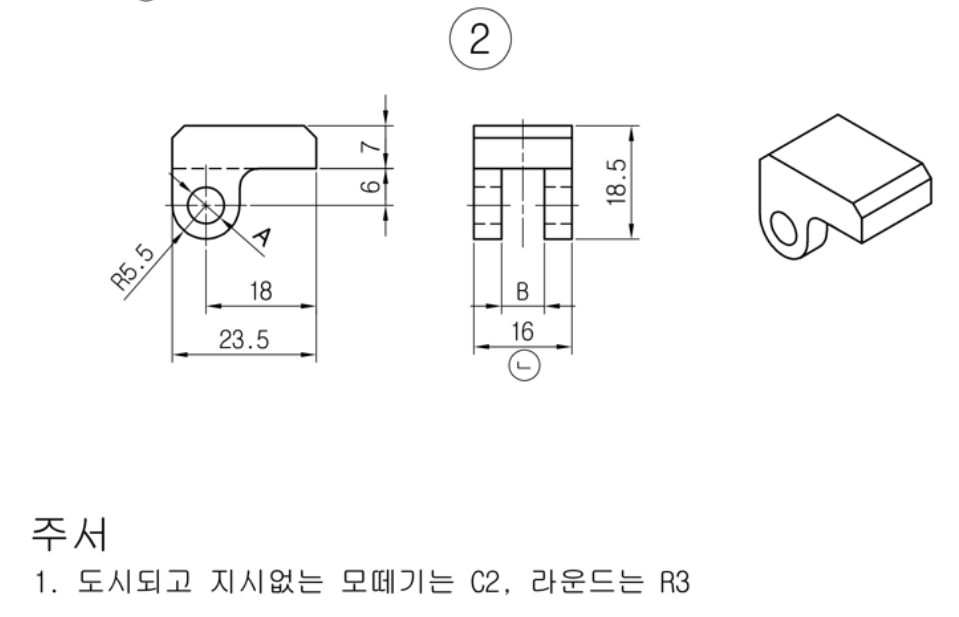
A : ∅6
-> This is where ∅5 from part 1 joins. Since we are modeling for FFF (FDM) 3D printing, we give +1 tolerance.
-> 부품 1의 ∅5와 결합되는 위치이다. FFF(FDM)방식의 3D프린팅을 위한 모델링이므로 여유공차를 +1을 준다.
B : 7
-> This is where 6 from part 1 joins. Since we are modeling for FFF (FDM) 3D printing, we give +1 tolerance.
-> 부품 1의 6과 결합되는 위치이다. FFF(FDM)방식의 3D프린팅을 위한 모델링이므로 여유공차를 +1을 준다.
Part 2
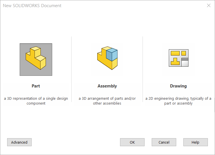
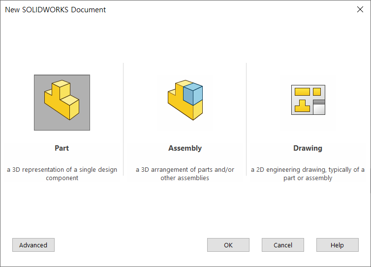
New -> Part
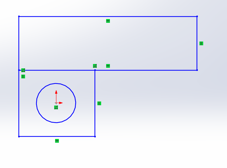
The origin is a good place to start if you know where Part 1 and Part 2 will be assembled.
부품1과 부품2가 조립되는 위치를 원점으로 정해놓으면, 기준을 정하기 좋다.
You can think of the dimensions as replicating the dimensions in the drawing.
Sketch with the multisketch method.
치수는 도면에 나와있는 치수를 그대로 옮겨놓는다고 생각하면 된다.
다중스케치방법으로 스케치한다.
Adding dimensions that aren't in the drawing can be a tricky thing for beginners.
Sketches appear black when they are fully defined.
도면에 없는 치수를 넣는건 초보자에게는 놓치는 요소가 많을 수 있다.
스케치는 완전정의가 되면 검은색으로 나타난다.
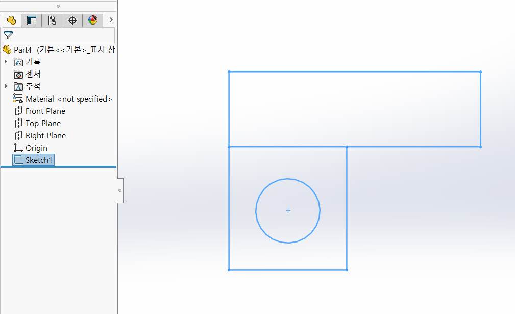
Finish the sketch with a multisketch method.
다중스케치 방식으로 스케치를 마무리 한다.
Select Regions with the same thickness,
Extrude Direction: Extrude from the mid-plane since it is symmetrical when viewed on a top plane.
같은 두께를 가지는 영역을 선택하고,
돌출방향 : 평면도를 봤을 때, 대칭형상이므로 중간평면을 기준으로 돌출한다.
Select a Region for the extrusion cut on the right,
the extrusion direction to be the midplane.
Set A=7
오른쪽 돌출-컷에 대한 영역을 선택하고,
돌출방향은 중간평면으로 한다.
A=7로 입력
The basic shape is completed.
기본형상은 마무리 되었다.
The bottom fillet is R5.5
아랫부분 필렛은 R5.5
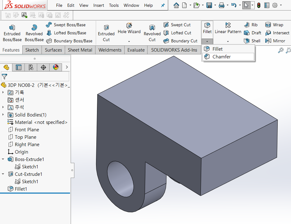
Make a chamfer.
모따기를 한다.
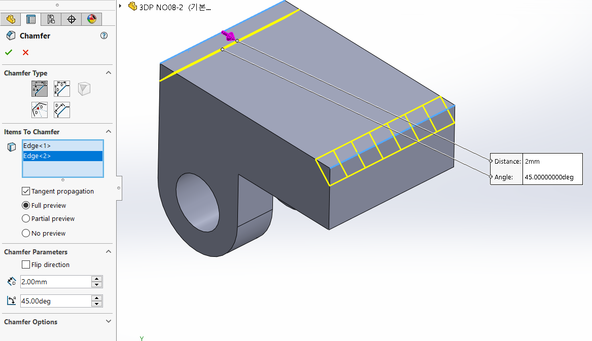
The chamfer dimension is C2
모따기 치수는 C2
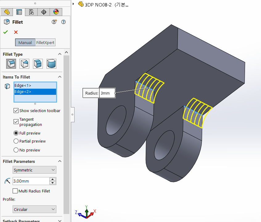
The round shown and uninstructed is R3
도시되고 지시없는 라운드는 R3
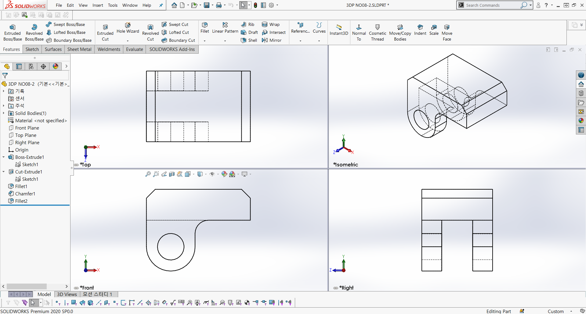
Part2 is Finished
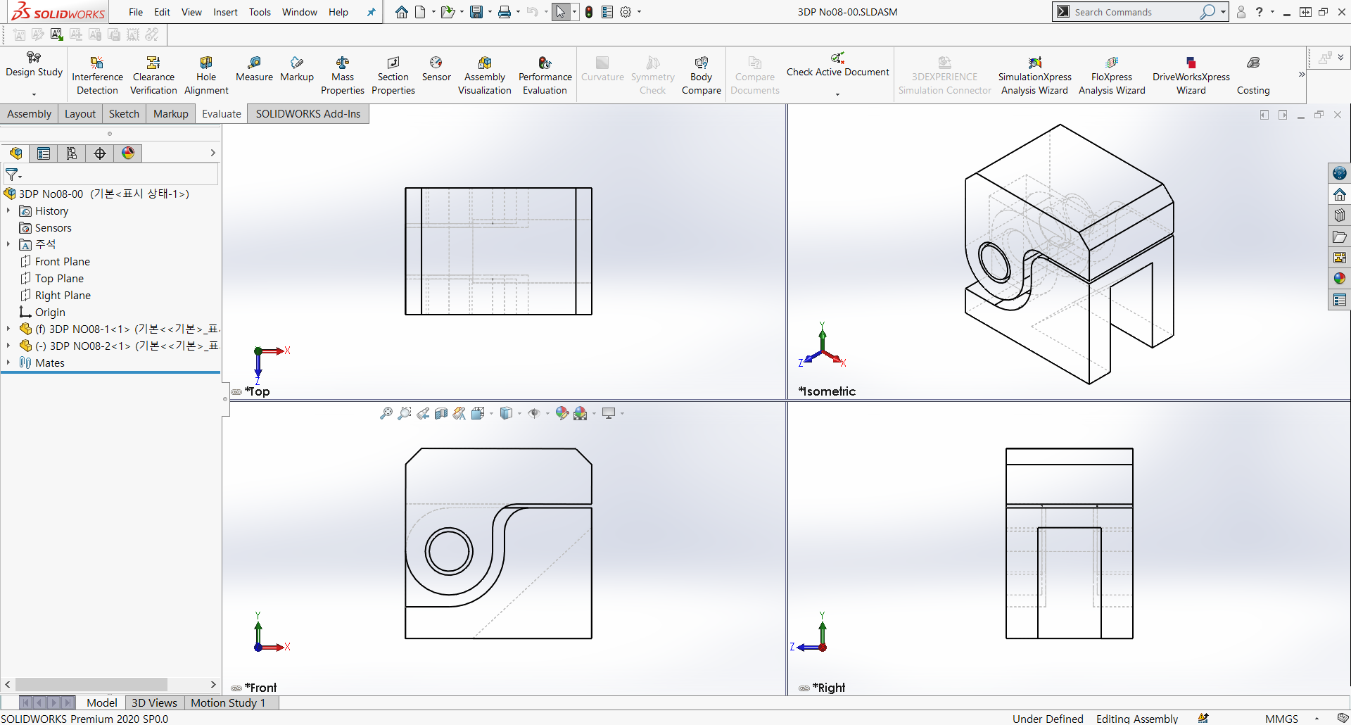
CHAPTER 2. ASSEMBLY
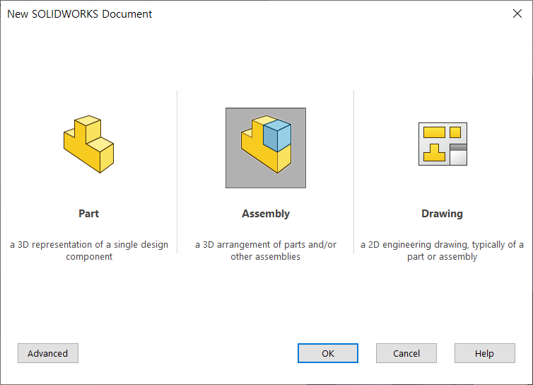
Start assembly
어셈블리 시작
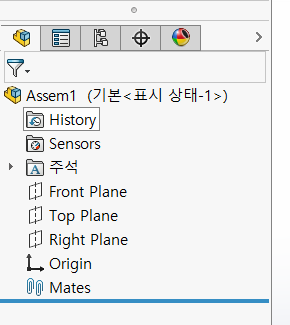
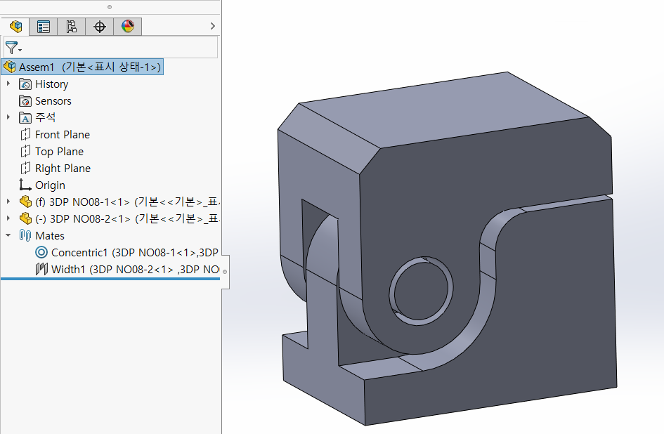
The main screen for parts and assemblies is almost identical.
The most noticeable are the icons at the top and the mates at the bottom.
파트와 어셈블리 기본 화면은 거의 동일하다.
가장 눈에 띄는건 맨 위의 아이콘모양과 맨 아래 메이트가 있다.
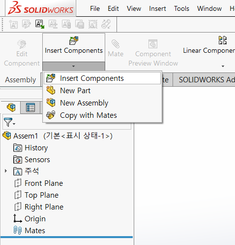
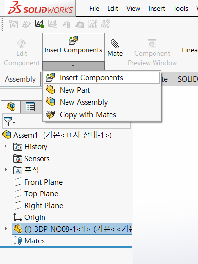
Assembly -> Insert Parts
어셈블리 -> 부품삽입
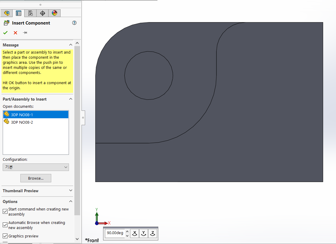
The base part is fetched and positioned first.
기준이 되는 부품을 제일 먼저 불러와서 자리잡는다.
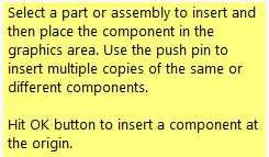
Select a part or assembly to insert and then place the component the graphics area,
Use the push pin to insert multiple copies of the same or different components.
Hit OK button to insert a component at the origin
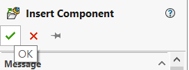
It is recommended that you click the checkbox right away to place the first imported part at the origin (important).
맨처음 가져오는 부품은 원점에 위치하기 위해 확인란을 바로 클릭해주는것이 좋다.(중요)
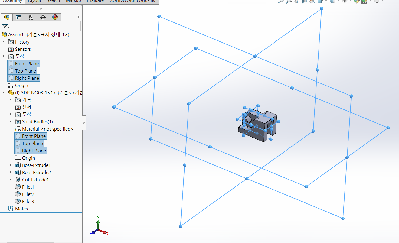
The planes and origin of the assembly and the planes and origin of the reference part are matched.
The first imported part is fixed with “(f)” because it is locked in place.
어셈블리의 평면들과 원점, 기준부품의 평면들과 원점이 일치된 모습.
제일 처음에 가져온 부품은 제자리에 고정기 때문에 부품명 앞에 "(f)"가 붙어있다.
Select 'Insert Part' again to import the second part.
2번째 부품을 가져오기 위해 다시 '부품삽입'을 선택한다.
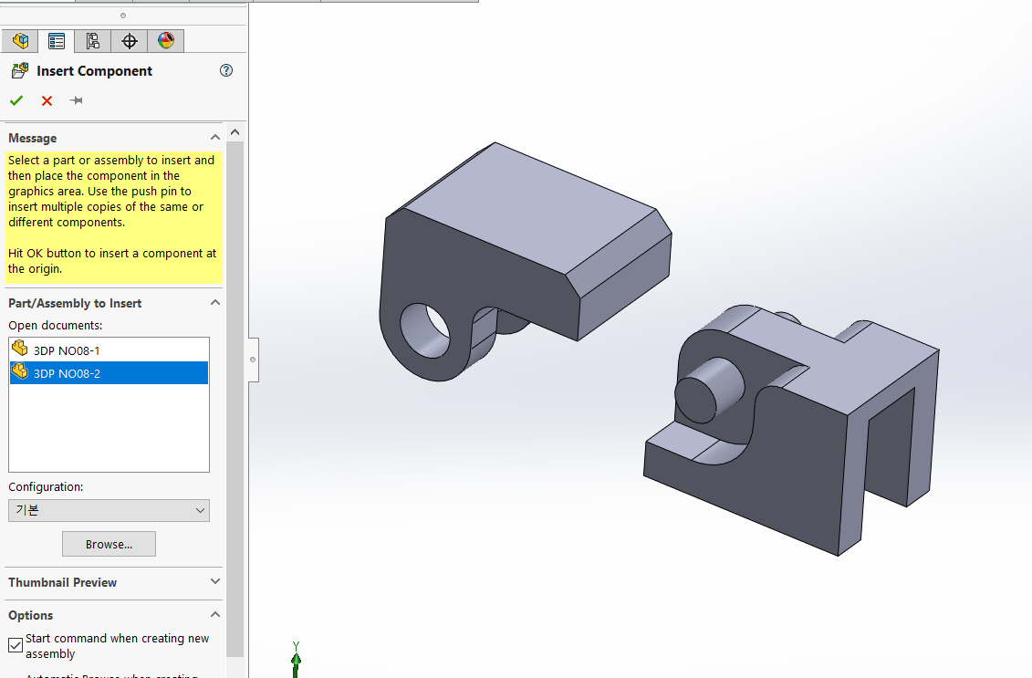
Starting with the second part, click and place it in the graphic area close to where it will be assembled.
2번째 부품부터는 조립될 곳과 가까운 그래픽영역에 클릭하여 배치한다.
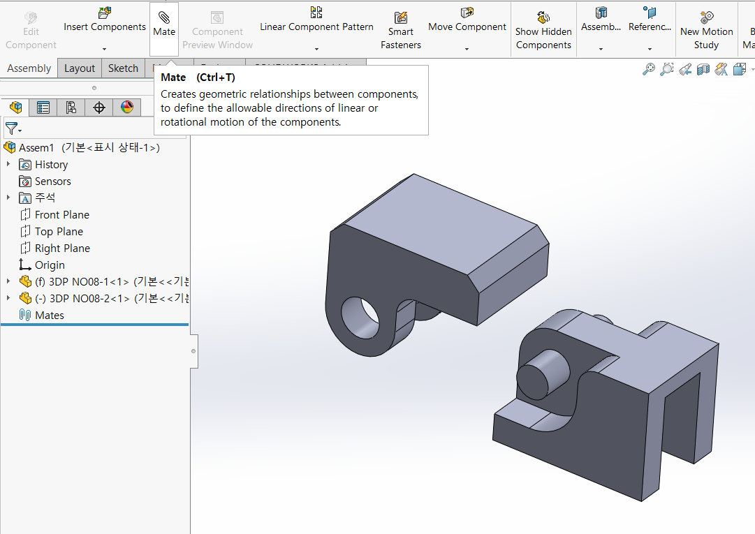
Select a “mate” to assemble the part
부품조립을 위해 "메이트"선택
It usually takes three mates to make a part “fixed” after assembly.
It usually takes two or more mates to get the parts to “work” after assembly.
부품들간의 조립 후 고정이 되게 하기 위해서는 일반적으로 3번의 메이트를 한다.
부품들간의 조립 후 작동이 되게 하기 위해서는 일반적으로 2번 이상의 메이트를 한다.
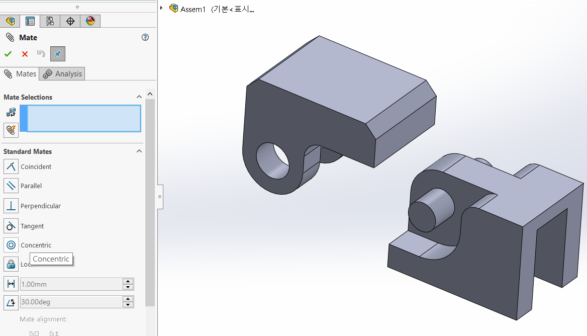
It is recommended to assemble the concentric elements in StandardMate first.
표준메이트에서 동심에 해당하는 요소들을 먼저 조립하는게 좋다.
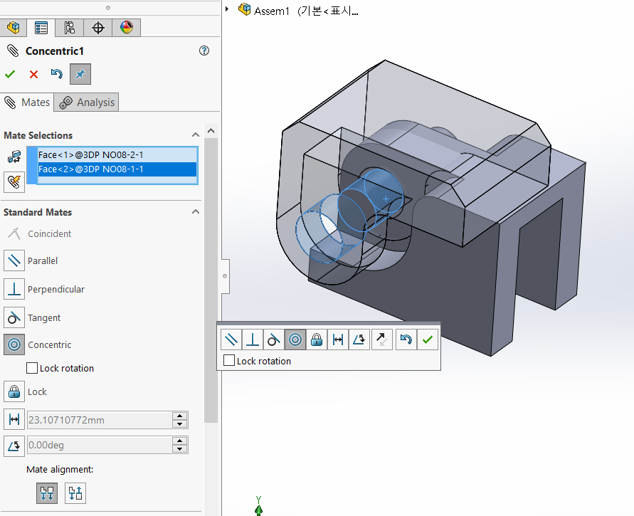
If there are no assembly issues, click the OK button.
조립 상 문제가 없으면 확인버튼을 누른다.
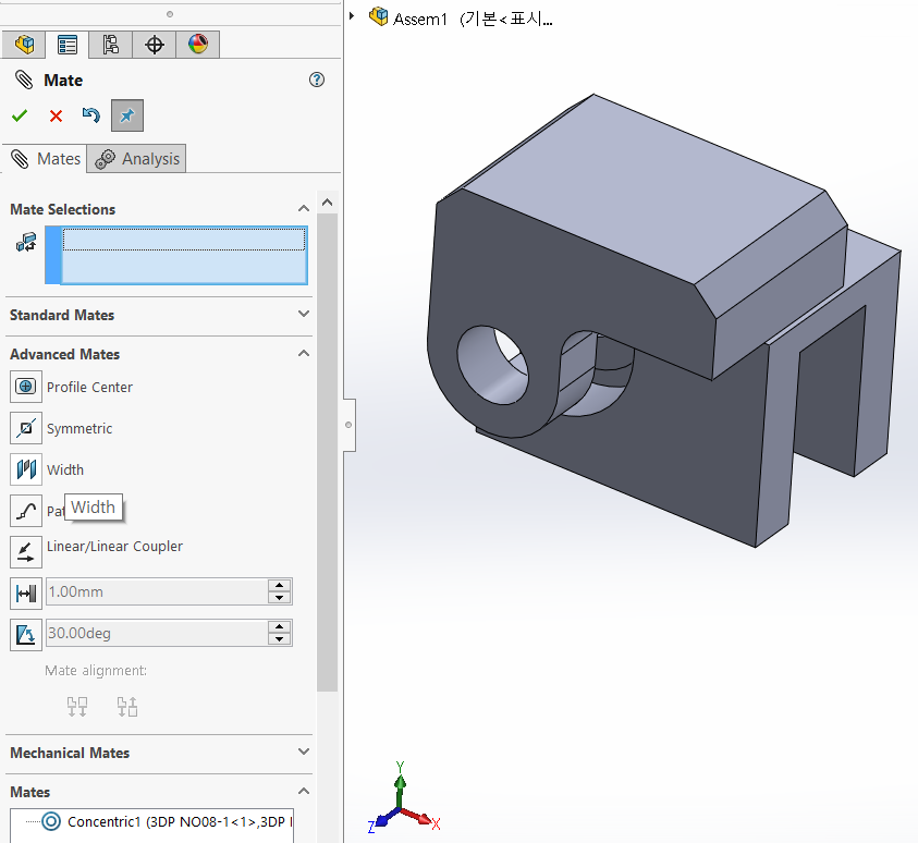
Select “Advanced Mate -> Width” to center the left and right widths.
좌,우 폭의 중심을 맞추기 위해 "고급메이트 -> Width"를 선택한다.
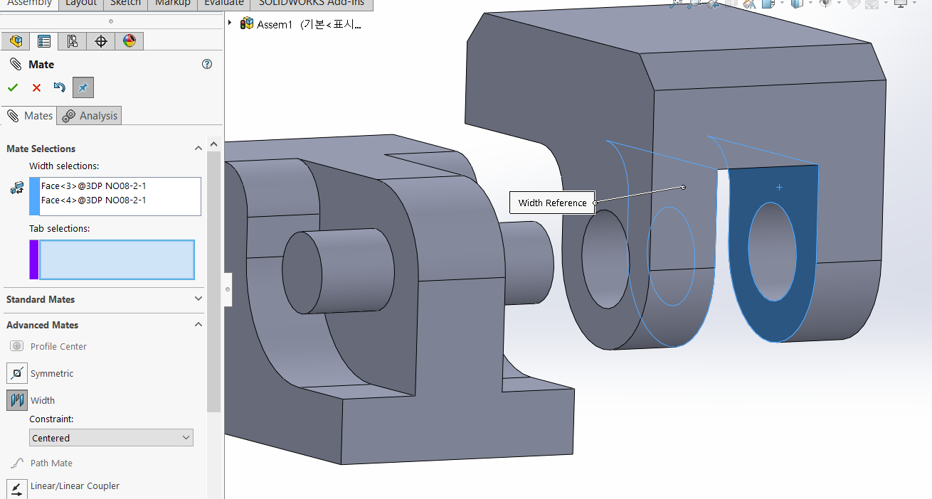
Select two sides that are the width.
폭이 되는 두 개의 면을 선택한다.
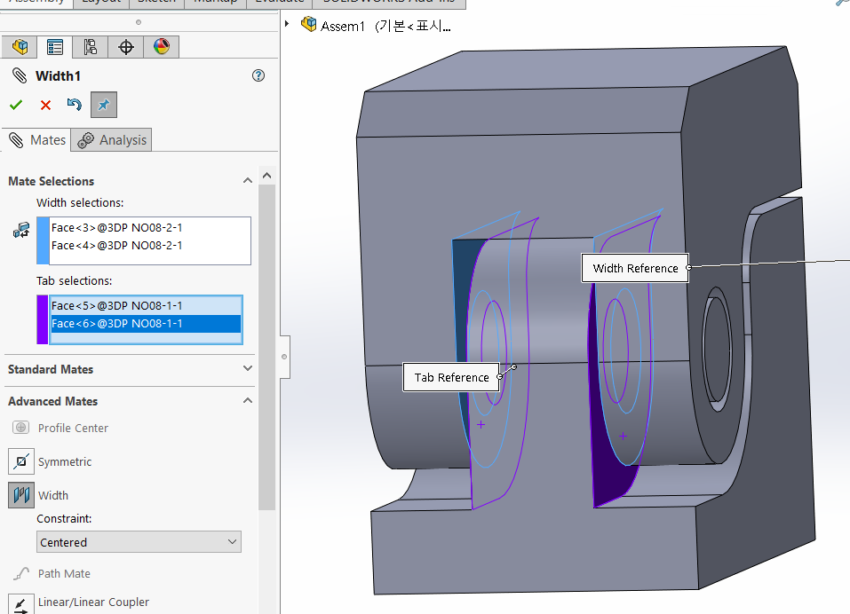
Select another two faces that Tab
Select a total of four faces.
대상이 되는 또 다른 면 두개를 선택한다.
총 4개의 면을 선택한다.
(It doesn't matter which set of two paired targets you choose first.
쌍이 되는 대상 2개 세트는 무엇을 먼저 선택해도 상관없다.)
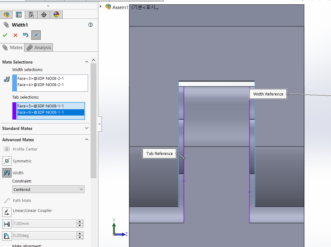
In your design, make sure the part is always centered, even if the size of the gap changes.
설계 시, 틈의 크기가 변하더라도 부품이 항상 중앙에 위치하도록 합니다.
The second part is a working part after assembly, so it only needs to be assembled twice.
두번째 부품은 조립 후 작동하는 부품이기 때문에 두 번만 조립해도 된다.
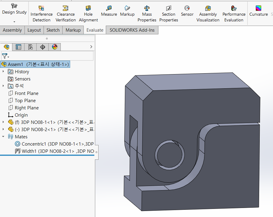
It is recommended to check for interference (overlap) between parts by selecting “Evalute - Interference Detection”.
부품간의 간섭(겹침)이 있는지, "Evalute - Interference Detection"을 선택하여 확인하는 것이 좋다.
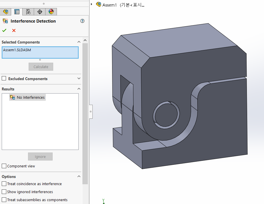
The assembly you are currently working on will be automatically applied, and you can press “Calculate” to check for anomalies.
현재 작업중인 어셈블리가 자동으로 적용되며, "Calculate"를 눌러서 이상유무를 확인한다.
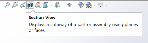
Section View를 선택해서 부품간의 간격도 확인해본다.
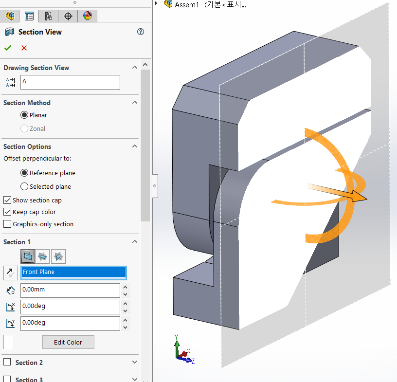
Check against the Front Plane
Front Plane을 기준으로 확인
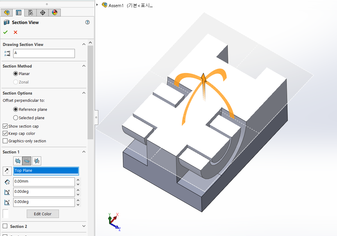
Check against the Top Plane
Top Plane을 기준으로 확인
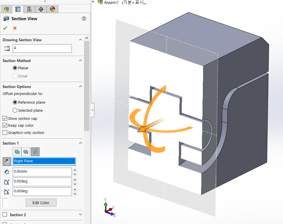
Check against the Right Plane
Right Plane을 기준으로 확인
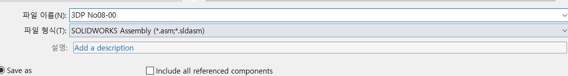
Save the assembly
어셈블리 저장
'3D PRINTING' 카테고리의 다른 글
| eyecontact 3D프린팅 실시간견적 (0) | 2025.01.25 |
|---|---|
| QGIS 대한민국지리 3D (3) | 2024.09.08 |
| 3D PRINTING 비케이원 202409 (0) | 2024.09.06 |
| CR-SCAN Feffet Pro (0) | 2024.07.08 |
| CR-Scan Ferret Pro (0) | 2024.07.02 |


